For many years, tin-lead alloys have been the primary surface coating for press-fit pins or vias in solder-free connections, due to their suitable insertion and holding force, high reliability, and low tendency for whisker formation. Until this year tin-lead coated press-fit pins are exempt from the RoHS Directive 2002/95/EC [1], which bans lead in electronics. So manufacturers will soon need to fully remove tin-lead to comply with these regulations. As a result, major connector manufacturers are increasingly adopting lead-free products, replacing tin-lead with 0.3 - 1 μm thick lead-free coatings [2,3,4]. However, pure tin alternatives face the challenge of whisker growth, especially as electronics move towards smaller pins and finer pitches, which can cause short circuits. Therefore, leading electronics manufacturers are still seeking reliable, RoHS-compliant alternatives to tin-lead coatings.
An alternative which is RoHS (Restriction of Hazardous Substances)-compiant is DuPont’s patented alloy Silveron GT-820 Silver-Tin, a cyanide-free electrolyte that produces a silver-rich silver-tin alloy with about 80 wt% of silver and a texture equal to ε-Ag3Sn and ζ-Ag4Sn intermetallic compounds. A uniform fine-grained AgSn20 microstructure and a stable alloy composition can be obtained over a current density range from 0.1 to 10 A/dm2. Higher current density can be achieved by increasing the bath agitation. With a suitable activation method, the AgSn20 layer gives excellent adhesion on nickel and copper-alloys commonly used for connectors. The electroplating of the AgSn20 alloy can be done by rack plating or by reel-to-reel selective plating.
This work describes the influence of the process parameters on the friction coefficient of a thin AgSn20 layer versus different commonly used printed circuit board finishes. The whisker test result, the insertion, and the retention forces of the AgSn20 layers produced under standard industrial conditions will be also disclosed. This qualification work was done in collaboration with Robert Bosch GmbH and ept GmbH to release the AgSn20 deposit for various automotive press-fit connectors.
Experimental
AgSn20 samples used for all performance tests were plated using the Silveron GT-820 Silver-Tin process. A Design-of-Experiment (DOE) was used to define and to study the process window by using both hull-cell method and the production line. The bath composition was adjusted to the desired formulation using product components Silveron Silver Solution, Solderon Tin Concentrate, and the SilveronTM GT-820 Silver-Tin Booster (available from DuPont Electronics and Industrial) to adjust silver, tin, and the free complexing agent (FCA) concentrations, respectively.
The thickness and alloy composition of different AgSn20 deposits were measured using a Fischer scope X-Ray Model XDV-μ (from Helmut Fischer AG) using a specific “Product 43001” measurement method and different AgSn20 standards provided by the company for calibration.
For the friction coefficient measurements, thin AgSn20 was plated on a metallic sphere of 6 mm diameter. The sphere (sliding part) was mounted on the suitable tool of a CSM Instruments wear device which operated with 1 N normal load. Printed circuit board (PCB) substrates with different finishes such as immersion tin, organic solderability preservative (Cu-OSP) were used as the static flat part. Both PCB types were tested as received and after a double reflow cycling. In each case, ten wear cycles were performed to record the coefficient of friction (COF) of the first cycles and the highest COF value. This test condition is just to compare different finishes but not a direct simulation of pin insertion into a plated-through-hole (PTH).
The insertion force, the retention force, the climatic tests, and the whisker tests were performed at Robert Bosch GmbH and ept GmbH according to IPC-9797 specification. A cross-section of the circuit board with pins was done to evaluate the contact or the possibility of metallic bonding between the AgSn20 finish and the PTH coating.
Results and discussion
The existing press-fit pins for automotive industry are made of copper-base alloys coated with a nickel underlayer and a pure tin or tin-lead top layer. The Bosch standard thickness of the top layer is between 0.35 and 0.75 µm. The thickness of AgSn20 deposit used in this test was the same as the classical system. For such a thin layer of AgSn20, the accurate estimation of the alloy composition and the thickness is challenging, particularly when the base material contains a fraction of tin (such as CuSn6 substrate) in the composition. Working in collaboration with the equipment supplier was helpful to design measurement method (Product 43001) which can be implemented on existing XRF devices and used for accurate estimation of the alloy composition and thickness. In the case of copper-tin alloy substrates, the program can be adjusted to correct the tin contribution from the base material. The program was previously calibrated using different AgSn20 standards provided by the XRF supplier. In addition, the choice of the XRF collimator size is very important for the accurate measurement at the functional area of the press-fit pin. As a result, the alloy composition of thin AgSn20 was shown to be stable at around 22 to 23.5 wt% of tin over the current density range. The composition was less dependent on the metal concentration ratio in the bath. Comparable results were obtained with thick (~2 μm) AgSn20 layers.
Figure 1 displays the coefficient of friction (COF) of a 0.5 μm silver-tin deposit versus Cu-OSP board as a function of the bath composition. The COF of this combination is very stable at around 0.257 over the current density range and the composition of the plating bath.
 Fig. 1: Influence of the silver-tin bath composition on the COF of 0.5 μm AgSn20 vs Cu-OSP-finished PCB
Table 1 summarizes the average coefficient of friction of the intermetallic AgSn20 deposit with other PCB finishes. The COF of the silver-tin deposit is comparable to tin-lead finishing under the same type of PCB final finishes. In each case, the deposit can provide the low coefficient of friction required for automotive press-fit connection. Such values will automatically reduce the insertion force. Testing on PCB finishes without reflow is only for comparison purposes. For real applications, PCB will always undergo a reflow process.
Tab. 1: Coefficient of friction of silver-tin deposit on different PCB finishes Sliding part PCB Static part Thickness on sliding part Average COF
|
Sliding part |
PCB Static part |
Thickness on sliding part |
Average COF |
|
AgSn20 |
Immersion Sn |
0.5 μm |
0.3 |
|
AgSn20 |
Immersion Sn + 2 reflow |
0.5 μm |
0.2 |
|
AgSn20 |
Cu-OSP |
0.5 μm |
0.25 |
|
AgSn20 |
Cu-OSP + 2 reflow |
0.5 μm |
0.35 |
|
AgSn20 |
AgSn20 |
3 – 4 μm |
0.4 |
|
Matte Sn |
Immersion Sn |
1 μm |
0.7 |
|
Matte Sn |
Cu-OSP |
1 μm |
0.34 |
|
Sn-Pb (90/10) |
Immersion Sn +2 reflow |
1 μm |
0.39 |
|
Sn-Pb (60/40) |
Immersion Sn +2 reflow |
1 μm |
0.39 |
|
Sn-Pb (90/10) |
Cu-OSP |
1 μm |
0.32 |
|
Sn-Pb (60/40) |
Cu-OSP |
1 μm |
0.3 |
Insertion and retention force of silver-tin deposit for solderless interconnections
For press-fit technology, solid connector pins are inserted by force in a plated-through-hole (PTH). During the press-in process, a high force can be established between the pin and the PTH, leading to the elasto-plastic deformation of the hole and the pin. In case of extreme force and deformation, the connection will be damaged. This can be mitigated not only by using a flexible press-fit pin design but also by selecting material with low coefficient of friction for pin finishing. On the other hand, a decrease in the normal force after pin insertion will affect the reliability of the contact. A very low retention force will decrease the contact load capability. Therefore, a suitable balance must be found to reduce the insertion force in each contact without compromising the required retention force [5, 6].
Figure 2 summarizes the insertion and the retention force of silver-tin coated signal contact pins in a PCB-through hole coated with Cu-OSP. Samples plated under serial production conditions on signal contact pins of 0.6 mm thickness were tested. Three different PTH diameters having the minimal, the nominal, and the maximal value were selected for the qualification test. Two times reflow was applied as pre-conditioning for the PCB according to the IPC-9797 specification. The retention force after 24 h at ambient storage is about 50 % of the insertion force. Those values are slightly lower as compared to pure tin on similar products. In general, the retention force decreases after various environmental aging. In the case of thermal cycling and climatic testing, this is assigned to the relaxation of the PCB material. This behavior is independent from the PCB surface finish. In each case, the insertion and the retention forces of silver-tin coatings were within the specification limit before and after aging; most of them were lower than pure tin finishes. The absolute value of the insertion and the retention force is dependent on the pin geometry and the surface finish of the PTH. A comparable result (not shown in the graph above) was generated using other press-fit pins, such as 0.8 mm power contact pins.
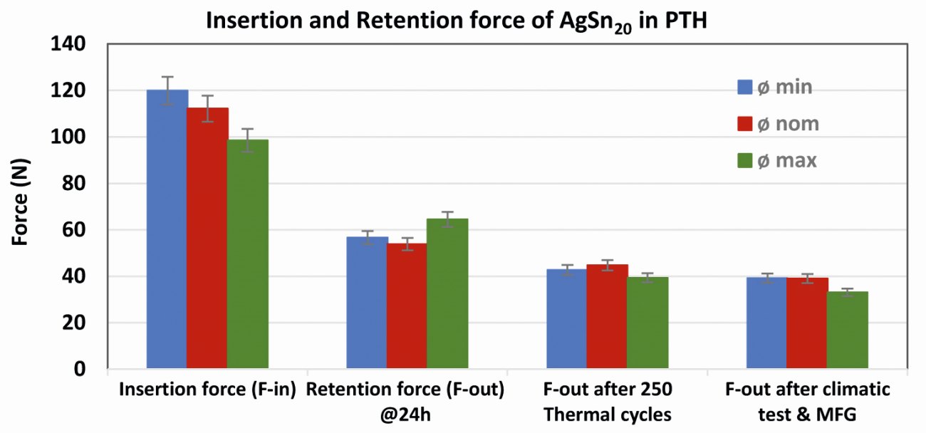 Fig. 2: Insertion and retention force of AgSn20-coated signal contact pins in Cu-OSP board before and after aging test. Three through hole diameters labeled as minimal (min) Nominal (nom) and maximal (max) were tested. MFG referred to the mixed flowing gas test
Interaction between AgSn20-coated pin and the PTH material
The press-fit system generally contains a press-in pin and the PTH. The functionality of such a system depends not only on the property of each of the components but also on their interaction. The press-fit pin incorporates a compliant mechanism which results in the elasto-plastic deformation during the insertion of pin into the PTH. Furthermore, the PTH undergoes deformation during pin insertion. Those deformations will significantly reduce the stress on PCB holes and provide sufficient normal force to establish good metal bonding between the pin surface finish and the PTH material. The metallic connection will provide the mechanical stability of the system and the low contact resistance required for electric signal transmission [2,7]. It is well known that such contact force between the compliant pin and the through-hole generates gas tight metallic bonding in the case of tin and tin-lead finishes. It was therefore important to make sure that a similar interaction exists between the AgSn20-finish and the PTH material.
The interaction between the AgSn20 press-fit pins and the PTH was tested under automotive qualification standard procedure by using pins plated at ept GmbH under serial production conditions. Samples were inserted into PTH using the suitable insertion device available at ept GmbH. Different cross-sections were performed, and the contact interfaces were studied using optical microscope and scanning transmission electron microscope (STEM).
Figure 3 shows optical images of the transversal and the longitudinal cross-section of the press-fit pin in the PTH. There is no excessive deformation of the copper inner layer and no excessive copper thinning on the wall of the PTH. This observation was valid for all PTH diameters and pin types tested. The nature of the contact between the PTH and the AgSn20 finish was further studied to check if there is evidence of metallic bonding between both materials.
 Fig. 3: Optical images of cross-section of AgSn20 pins inserted in the PTH
Figure 4 displays the high-resolution STEM image of the contact zone between the AgSn20 plated pin and the copper plated PTH. There is no visible copper diffusion from the PTH to the AgSn20 when the assembly is stored at room temperature. At the atomic level, there is no visible gap between the copper and the AgSn20. Through the contact pressure, a metallic bond was created between the copper and the AgSn20 layer. The crystalline structure of the AgSn20 alloy and copper are clearly visible on the transmission electron right hand side image of Figure 4. This suggests that AgSn20 create sufficient metallic connection with the PTH to ensure a good mechanical stability and suitable electrical conductivity through the system. In addition to the cross-sectioning, whisker test, electrical measurements, and other environmental tests were performed to confirm the reliability of AgSn20 deposit as material for press-fit interconnections.
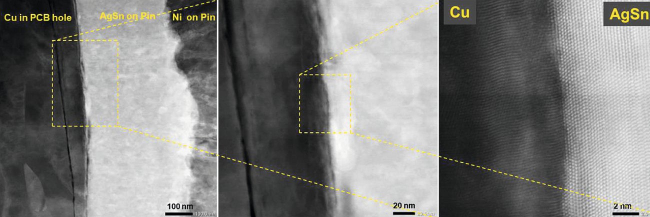 Fig. 4: STEM images of the contact zone between AgSn20 pin and the copper plated PCB hole
Whisker tests of AgSn20 press-fit connectors
Whisker tests were performed on AgSn20 deposit according to IPC-9797 specification using various PTH materials. Typical whisker data of a AgSn20-coated pin inserted in Cu-OSP-PTH is displayed in Table 2.
Tab. 2: Whisker test data of AgSn20-coated pin in Cu-OSP-PTH after 12 weeks at ambient storage
|
Whisker length Interval (in μm) |
Quantity of whisker |
|
1 to 50 |
6 |
|
51 to 100 |
1 |
|
101 to 300 |
0 |
|
301 to 500 |
0 |
|
501 to 1000 |
0 |
|
>1000 |
0 |
The AgSn20 / Cu-OSP-PTH system has short whiskers after 12 weeks storage at ambient conditions. Most whiskers were less than 50 μm in length; only one long whisker was found, but the length is still below 100 μm. For all samples, the quantity of whiskers was very low, owing to the absence of free tin phase in the AgSn20 deposit. In general, whiskers should not be expected on ε-Ag3Sn material. The short whisker found after the insertion of AgSn20 into Cu-OSP-PTH can be assigned to the compression of the semi-amorphous AgSn20 deposit and the non-stochiometric ζ-Ag4Sn phase. It was discussed in a different paper that AgSn20 deposit is semi-amorphous after plating and can be converted to a fully crystalline material after annealing or long storage.
Comparable whisker test results were obtained using other PTH finishes such as immersion tin. Silver-tin whisker test results were encouraging because the whisker length and the whisker frequency were very low as compared to pure tin finish. This performance is comparable to tin-lead finishes and demonstrates that AgSn20 is a suitable new material for RoHS-compliant solderless interconnection.
Electrical tests on AgSn20 press-fit connectors
Press-fit connectors should also meet many other requirements under critical operating environment described in the IPC-9797 specification. This includes the mechanical function with low insertion force, acceptable retention force, and low through hole deformation should be preserved. All this contributes to the electrical functionality with the low contact resistance and the high current carrying capacity.
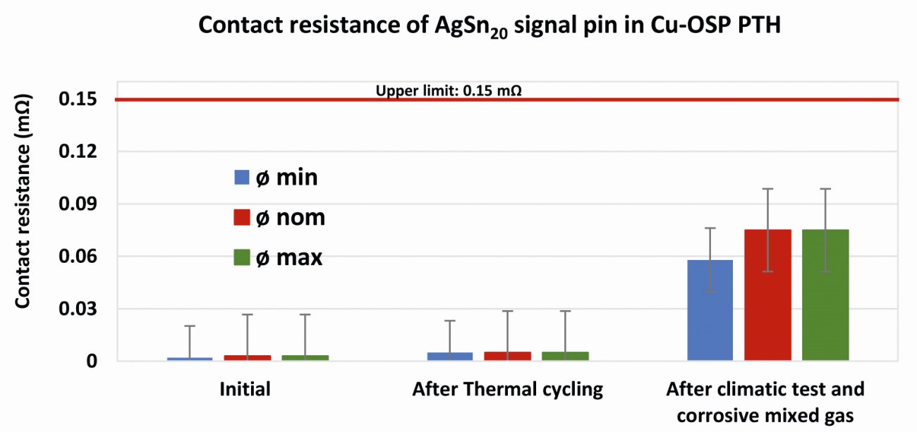 Figure 5: Influence of the aging conditions on the contact resistance of AgSn20 signal pins inserted into Cu-OSP PTH with different hole diameter
The contact resistance values of AgSn20-coated pins were measured under different aging conditions and the result is summarized in Figure 5. For all type of PTH diameter, the initial contact resistance of the system is very low. The values remain substantially low and stable after the thermal cycling test. In contrast, the high temperature test or the mixed flowing gas test has some impact on the contact resistance of the system. This is due to the corroded contact area of the external pin and the PCB surface finish. During the mixed flowing gas test, the contact area between the PTH and the pin did not react with the gas giving evidence that metallic bonding has been established and the gas tightness was effective at the contact area. This was not the case with the external part of pins used for electrical contact during the resistance measurement. This is supported by the stable retention force obtained under the same climatic test as shown in Figure 2. Nevertheless, the resistance value remains in range for this product type where the tolerance limit is set at 0.15 mΩ. Similar results were obtained with all designs and products tested. In all cases, resistances were within the specification before and after aging. The silver-tin coating met the electrical requirements for press-fit interconnections.
Examples of pin coated with AgSn20 for qualification
Figure 6 displays one example of an automotive press-fit pin coated with silver-tin coating and optical images after insertion in the PTH. All pins plated under industrial serial production were shiny before and after insertion. Flakes, bulging and copper cracks could not be identified after pin insertion into PTH before and after aging test.
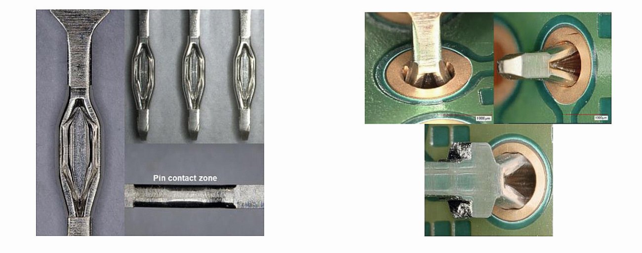 Figure 6: Image of a typical Press-fit pins coated with nickel and AgSn20: a) different view; b) after insertion in Cu-OSP-PTH
Conclusion
Leading automotive electronics manufacturers are looking for a reliable and RoHS-compliant solution. Their priorities are lead-free finishes which are not susceptible to tin whiskers but have comparable or better performance to press-fit connections using standard tin-lead finishes. DuPont Electronics and Industrial has developed a viable AgSn20 process for lead-free coatings on compliant pins. This surface finish is compatible with all standard lead-free PTH finishes like immersion tin and Cu-OSP.
The qualification of the complete press-fit pin done according to the IPC-9797 specifications, confirmed that the material met the insertion force, retention force, and contact resistance requirements for solderless interconnections. The silver-tin deposit can interact with the PTH material at the atomic level to create a gas tight metallic bonding. Such intimate connection is responsible for the low contact resistance and the suitable retention force observed for the material. In all cases, the contact resistance and the retention force were within the specification after different climatic tests. This makes Silveron GT-820 process and the corresponding silver-tin deposit a suitable candidate for pure-tin and tin-lead replacement for press-fit connectors.
Serial production at the industrial level confirms that the Silveron GT-820 Silver-Tin process is suitable for the manufacturing of silver-tin deposit with about 79 wt% of silver. The chemistry is stable, and the quality of the deposit is constant within a broad process window defined in a DOE matrix. Particularly, a variation of the current density or a small change in the metal concentration ratio did not have impact on the deposit. Based on the above performance and many other industrial data, leading automotive electronics manufacturer such as Robert Bosch GmbH have already qualified and released the Silveron GT-820 Silver-Tin process and the corresponding AgSn20 deposit for press-fit applications.
+++Wissens-Fakts+++Wissens-Fakts+++Wissens-Fakts+++Wissens-Fakts+++
Der Wert des Silbers
Silber hat seit der Antike einen hohen Wert und wurde in vielen Kulturen als Edelmetall geschätzt. Es wurde als Währung, Schmuck und für Kunstgegenstände verwendet. Silber ist das bestreflektierende Element und hat eine außergewöhnliche Fähigkeit, Licht zu reflektieren. Diese Eigenschaft macht es zu einem wichtigen Bestandteil von Spiegeln, Teleskopen und fotografischem Film. Es ist einer der besten elektrischen Leiter und wird daher häufig in elektronischen Komponenten wie Leiterbahnen, Schaltern und Steckverbindern verwendet. Außerdem wird Silber in der Photovoltaikindustrie eingesetzt, um Solarzellen herzustellen. Es bildet eine leitende Schicht, die den erzeugten Strom effizient ableitet.
References:
[1]Directive 2002/95/EC of the European Parliament and of the Council, of 27 January 2003 on the restriction of the use of certain hazardous substances in electrical and electronic equipment; Official Journal of the European Union. (2003) L37/19.
[2]PRESS-FIT for the Automotive Industry, TYCO Automotive Catalog N°1654403-1 revised_2016
[3]3M Product Discontinuation Notice n°830, 1 October 2012: CP2 Press-Fit Connectors – Tin-Lead plated parts to be replaced with Tin-Plated parts.
[4]George J.S. Chou & Robert D. Hilty; “Effects of Lead-Free Surface Finishes on Press-Fit Connections”; Proceedings of The IPC Annual Meeting, Minneapolis, Sept- Oct. 2003.
[5]Helmut Katzier; Elektrische Steckverbinder Technologien, Anwendungen und Anforderungen; Eugen G. Leuze Verlag, ISBN 978-3-87480-273-4 (2012) 69-73.
[6]A. Kerkhoff; Compliant Press-Fit Technology Integrated into a new Back Panel Packaging Approach; Electrocomponent Science & Technology (1984) 11, P165.
[7]Dante Parenti & Jack Mitchell; Validating Press-fit connector Installation. Circuits Assembly (2003)26.

